Detector Geometry and Corrections
Documentation notice
This documentation was generated with help from a large language model and has not been fully vetted by the developer. Verify critical details against the source code and current application behavior.
This section covers how EWALD maps detector images to corrected q<sub>xy</sub>/q<sub>z</sub> space.
For the reciprocal-space equations behind this mapping, see
Mathematical Foundations.
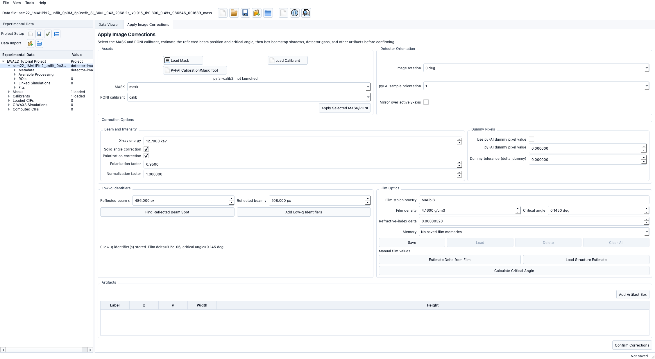
Detector orientation
EWALD tracks:
- image rotation (0/90/180/270 degrees)
- optional mirror
- derived pyFAI sample orientation value
Use these values to align raw and corrected frames.
Masking
EWALD stores mask assets and applies them in correction and integration steps.
- Load masks from file.
- Assign masks to targets before confirmation.
- Artifact regions (beamstop, gaps, hot pixels) can be added to the correction table.
Correction options
Correction settings include:
- solid-angle correction
- polarization factor
- normalization factor
- optional dummy / delta_dummy exclusion
These are preserved on a per-target basis after confirmation.
Coordinate conventions
q<sub>xy</sub>andq<sub>z</sub>axes are shown in reciprocal-space viewers.q<sub>xy</sub>values usually span negative to positive in-plane projection.- Units are in Å-1 by default in UI display.
Definitions
q<sub>xy</sub>: in-plane reciprocal magnitude component.q<sub>z</sub>: out-of-plane reciprocal component.
Common mistakes
- Confirming corrections before correcting rotation/mirror.
- Applying one mask to geometrically different detector settings.
- Expecting downstream tabs before confirmation.
Planned / not fully available
- Some advanced detector-specific correction transforms are currently Experimental.